97% customer satisfaction based on last 45 days of sales
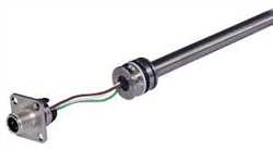
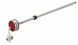
Mts Sensor MH SIL2 Mobile Hydraulic Position Sensor


Brand:
Product Code:
MH SIL2
Order Processing & Delivery Information:
As we supply industrial equipment, product availability and delivery timelines may vary. Once your order is placed, our sales team will contact you within 24 business hours (excluding weekends and holidays) to confirm stock status and estimated delivery time.
Product Documentation/Technical Datasheet
Tags and Keywords:
🎯 Need a Quote for Mts Sensor MH SIL2 Mobile Hydraulic Position Sensor?
Get the best price and fastest delivery for Mts Sensor MH SIL2 Mobile Hydraulic Position Sensor from Mts Sensor. Imtek Engineering offers worldwide industrial equipment supply with expert support.