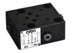
Produktname: Aron NG6 4/3 24V DC AM Directional Control Valve
Marke: Aron
Produktcode: NG6 4/3 24V DC AM Directional Control Valve
Stichwörter: Aron
NG6 24V Control
24V Directional Valve
4/3 Valve
NG6 4/3 DC AM Directional Valve
Aron NG6 4/3 24V AM Control
4/3 DC Control
NG6 AM Directional Valve
24V DC AM Directional
4/3 24V
Aron NG6 4/3 24V DC AM Control
Aron 24V DC AM
NG6 DC Directional
24V DC
Aron NG6 24V DC Control Valve
4/3 24V DC AM Valve
NG6 4/3 AM Control
Aron NG6 4/3 24V DC AM
Aron 4/3 24V DC Directional Valve
Aron Directional Control Valve
Interessieren Sie sich für das Produkt Aron NG6 4/3 24V DC AM Directional Control Valve vom Hersteller Aron mit dem Code NG6 4/3 24V DC AM Directional Control Valve? Kontaktieren Sie uns jetzt und holen Sie sich ein Angebot. Imtek Engineering, der schnellste und zuverlässigste Lieferant von Industrieausrüstung der Welt, wird Ihnen das beste Angebot machen!
Angebot per E-Mail erhalten: info@im-tek.com
Holen Sie sich jetzt ein Angebot für Aron NG6 4/3 24V DC AM Directional Control Valve von unserem Live-Support-Team!
ARON cartridge valves are basically composed of a cover and an operating unit insert in the ISO 7368 (DIN24342) mounting frame. Each cartridge valve is characterized by 2 main ways for the nominal flow (up to 350 l/min).By combining the various covers, operating units and connections within the block, may different functions can be obtained like: direct control, non-return, hydraulically piloted non-return, pressure control, flow rate regulation, as well as a combination of these same functions.Thanks to their design features and operational flexibility, cartridge valves can be used to speed up machine cycles, and therefore increase productivity and efficiency (Better response time compared to traditional valves);-ensure minimum thermal dissipation (tanks to the passageway dimensions)-reduce the hydraulic plant weight (tanks to the compact functions block)-reduce to a minimum any internal leakages-provide ease of installation and servingThe logic units 2/2 (Fig. 1) are formed by a cover (1), a functional unit (2), a spacer (3), a closure spring (4) and a guide bush (5) for each functional unit. The maximum allowed pressure is a function of the flow rate (max. 400 bar).