·
2 year warranty and 60 years of Dynisco industry experience·
Accuracy better than ±0.5%·
TiAlN diaphragm coating is standard·
mV/V, 0-10VDC, or mA outputs available·
Integral temperature sensor option·
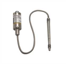
Available in configurations that fit most extruder applications·
1.5M, 3M, 5M, 7.5M & 10M psi pressure range capability·
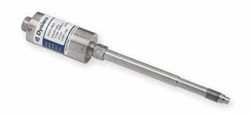
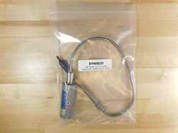
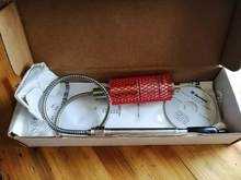
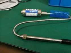
Alternative fill model available Operating Principle The Dynisco EchoTM Melt Pressure Sensors are used to make
pressure measurements of molten polymers up to 752°F (400°C). These models
incorporate a 350?Ohm, bonded foil strain gage Wheatstone Bridge. This proven
technology provides an output of 0?3.33 mV/V, & 4?20mA, 05?VDC and 0?10VDC
proportional to melt pressure (within the specified error band). Most models
include an internal shunt calibration ("Rcal") function that is used
to simulate a signal of 80% of full scale. This eliminates the need for a
cumbersome calibrated pressure source when scaling associated instrumentation. Installation Do not remove protective cap until ready to install. Prior
to initial installation, verify correct machining of mounting hole per Figure
1. Gauge Plug, P/N 200908, is available for this purpose. Before installing
make sure that mounting hole is clear of material. Dynisco Cleaning Tool Kit,
P/N 200100, should be used. To prevent galling, lightly coat transducer threads
with a high temperature anti?seize material. An adequate seal, in a properly
machined and maintained mounting well, is obtained with 100 in?lbs. mounting
torque. The maximum torque recommended is 500 in?lbs. The electronics housing
should be secured, with the optional mounting bracket (P/N 200941), in an area
where the ambient temperature will not exceed 185°F (85°C). (Mounting bracket
not supplied with EchoTM models.)Wiring Use shielded cable. Attach cable shield to ground at one end
only. NOTE: DYNISCO cable assemblies are constructed with shield wired to
transducer mating connector, so do not attach shield to instrument. Output
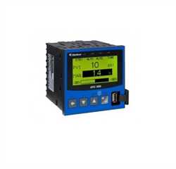
Supply Voltage mV/V 10 Vdc (12 Vdc max) mA 14?36 Vdc Vdc 16?36 Vdc Start?Up Bring system to operating temperature with no pressure. For
mA units, remove adjustment access screw and adjust Zero Output potentiometer.
For mV/V units, zero adjustment must be handled by downstream indicator. Make
sure that there is sufficient "soak time" to assure that any material
at the tip of the transducer is molten before extruder drive is started. Removal Transducer should only be removed when polymer is hot and
liquid. Wipe tip with a soft cloth immediately. The melt pressure transducer
must be removed before using an abrasive material or wire brush to clean the
extruder barrel. Clean the mounting well before attempting to reinstall the
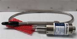
transducer with Dynisco Mounting Well Cleaning Tool Kit, P/N 200100. Thermocouple Thermocouples ( Type J or K) in a rigid stem are optionally
available. The Type J (iron?constantan) and Type K is a T/C junction just
behind the flush diaphragm at the tip of the transducer. For the most accurate
temperature measurement of the melt stream, use a separate immersion?type
thermocouple, such as Dynisco TB422 fixed depth series or (G)RMT adjustable
models. The thermocouple assembly can be removed by loosening the set screw on
the side of hex assembly and pulling the T/C probe, carefully, straight out,
without twisting. Replacement assemblies are available. When installing the
thermocouple probe assembly, align the slot with the pressure capillary tube
and press into snout until top of probe shoulders flush against snout. Lock in
place with set screw.Warranty
This Dynisco product is warranted under terms and conditions
set forth in the Dynisco Web Pages. Go to www.dynisco.com and click on
“Warranty” at the bottom of any page for complete details.