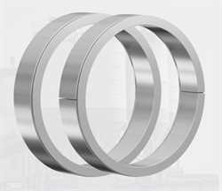
High-quality RINGFEDER® Locking Elements of the RfN 8006 series are used for friction-locked shaft-hub connections without screws. They are completely wear- and maintenance-free, extremely compact and flexible to deploy, easy to assemble and disassemble and guarantee users maximum reliability and precision. Our locking elements are available to users with an inner diameter from 6 to 1,000 millimetres as well as in slit and solid versions. They are particularly suitable for the failsafe transmission of low to medium axial loads and torques.
Product Characteristics
Your Benefits
Customised application – By varying the number of Locking Elements, size and quantity of clamping screws, the connection can be adapted to fit most applications concerning surface pressures, materials, hub/shaft dimensions and available mounting space.
Transmission of high loads – To increase the transmissible torque and axial forces up to 4 Locking Elements can be used in series.
Maximum reliability – No matter whether the connection is subjected to static, pulsating, dynamic or intermittent loads.
Simple manufacture – Shaft and hub are designed without keyway. Apart from this, relatively large tolerances are admissible.
Easy adjustability – Locking Elements work without positive connection. So they can be adjusted at any place to any position by following the simple installation and removal instructions.
Backlash-free – The locking element connection is a mechanical shrink fit and will not wear or loosen in service provided that the maximum transmissible values for the connection are not exceeded.
High fatigue strength under alternating torsional stresses – As neither the shaft nor the hub have grooves the notch effect is minimized and a higher polar section modulus is given, enabling the use of smaller diameters.
Simple installation – In comparison to cross-press fits temperature treatments and fitting are eliminated. Screws have to be tightened with standard tools.
Easy removal – Locking Elements are self releasing no additional measures or auxiliary equipment is required.
Wear and maintenance-free – Unlimited lifetime if designed and used correctly.
Mounting Of Locking Elements
The values for T and Fax, apply to Locking Elements installed in oiled condition.
Surface Finishes
For shafts and hub bores
Ra ? 1 ?m
Required Screw Tension Force
for Locking Elements solid: FA = FA´ + F0
for Locking Elements slit: FA = FA´
n-Locking Elements
Where n-Locking Elements are used one behind the other (series), the following applies to the increase in T and Fax:
Tn = T1 · m
Faxn = Fax1 · m
Retaining the values for T and Fax it is possible to reduce FA´ and p when using elements in series:
FA´n = FA´/m
PN = p/m
With 2 / 3 / 4 Locking Elements, m = 1.555 / 1.86 / 2.03
1) Approx. values, 2) Inner diameter, 3) Outside diameter
The fits specified have given excellent service in practical operations. Naturally, the shafts and the bores can feature other clearances. Please contact our engineering team for assistance.