EPM electrolytic starter can be used to start slipring motors from 500 kW to 20,000 kW. It will supply the power necessary to drive the motor by resistance variation. Designed for controlled starting and speed control of large slipring motors in demanding applications, the EPM liquir rotor starters ensure a smooth progressive acceleration of installations such as:VentilationCrushingMillingConveyorsPumps...They are widely used in various industries such as mines, quarries, cement plants, water treatment and associated industries. They are also adapted to specific applications such as car fragmentisers, plastic mixers and sugar cane knives.Several models and options are available according to the starting power required, the inertia of the driven machine and the application. Feel free to contact us and explain us about your requirements (Use the section Necessary information to quote a starter), our staff will quote the suitable starter and the eventual necessary options.You will find below the description of an EPM starter and its operating principle.
Necessary information to quote a starter
Driven machine:Type (Crusher, conveyor…)Rotor data: Motor power, rotor voltage, rotor currentMotor speed in tr / minSingle or dual assemblyAmbient temperature: Minimum, maximum and average valueStarting time in sTemps de démarrage : en secondesStarting torge: CnNumber of starts per hourNumber of consecutive startsCountry of destination
Description
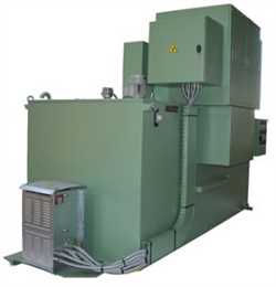
An EPM unit is made of:the electrolytic resistance contained within a tank complete with electrodes of a size rated for the specific kW rating.the MV enclosure housing the short-circuit contactor.the LV enclosure which contains the control system.Tank: The tank is manufactured with heavy duty sheet steel 30/10 to 50/10 mm gauge, and is normally supplied complete with lifting eye bolts Tank capacity and dimensions are determined by the motor rating.The tank is filled through a filling flap and emptied through valves situated at the base of the unit, which are normally locked in the ‘closed’ position.Agitator: The agitator is thermostatically controlled to ensure maximum thermal capacity.Electrolyte: Various concentrations of sodium carbonate are normally employed. The electrolyte level is monitored by a float switch and the temperature is controlled by thermostats.Electrode assemblies: A set consists of three fixed and three moving electrodes; polypropylene containers shroud the fixed electrodes to provide adequate isolation between phases.The cast alloy electrodes consist of concentric cylinders which merge with each other in the minimum resistance position.The fixed electrodes, located inside the insulating containers, are fed from an insulated copper bar. Since this bar does not pass through the tank wall, there is no danger of electrolyte leakage.The moving electrodes travel vertically inside the insulating container, guided by a nylon rod. The assembly is supported by two brass rods fixed to a transversal carrier which is common to all three electrodes and constitutes the neutral point.Current density is extremely low (typically 1 amp/cm²) resulting in extremely long electrode life.Electrode control system:Displacement of the electrodes is effected by a motor driven worm screw assembly. This is normally controlled by either a geared motor or a servomotor depending on the application.An inverter may also be used for some applications.A hand wheel is also provided for emergency operation.Starting times are adjustable from 10 to 150 seconds.Control and interlocking: Limit switches are incorporated to control the geared motor, and to power the shorting contactor which shorts out the residual resistance at the end of the run up time. The geared motor is fitted withan overload relay, which is used to provide protection in case of the drive mechanism jamming.An electrical interlock prevents a restart before the electrodes return to the initial maximum resistance position.If a power failure occurs during starting, the electrodes return automatically to the start position when the supply is restored, so that a new start is possible.Control panels: The control gear is housed in two separate enclosures. The shorting contactor complete with the rotor terminations are housed in the MV enclosure.A separate housing is provided for the LV controls.The MV enclosure is normally included with the starter, but for higher ratings, it may be supplied in a separate control panel.
Operating principle
The EPM rotor starter is normally used to control the starting of a slipring motor, and the starting current is generally limited to a maximum of 250% FLC.Optimal starting torque for each application is normally selected by the choice of the initial value of resistance.The principle of the EPM starter is that the resistance automatically varies during the starting pe riod.This type of starter is designed to provide the optimum starting characteristic, which results in smooth progressive acceleration to full load speed. It can also be used for speed variation and torque control. Plug braking can also be implemented with this system.The variation in the resistance is achieved by displacement of the electrodes in the electrolyte.At the end of the acceleration, the electrodes are short-circuited.
Advantages of AOIP starters for slipring motors
Smooth progressive acceleration, slowing down possible by reintegration of the resistanceSuitable for a wide range of standard and specific applications:Resistance value can easily be modified, even by the userElectrodes can be manually controlledPossibility to combine a servomotor and a heat exchanger for high power applications with frequent starting and / or speed variationStandard starting time (factory preset): 20 s, 30 s, 40 s, 60 s, 80 s and 130 s. (In option, for a starter equiped with a speed variator, adjustable starting time from 5 s to 300 s)Rotor voltage up to 3,500 VPossibility to couple two EPM synchronized together for high power motors, to drive simultaneously two identical motors or to reduce mechanical stressTropicalisation, antifreeze heater, anti condensation system, heat exchanger… Robust and reliable equipment:Reduced maintenance (replacement of electrolyte every 10 years)Level of electrolyte controlled by magnetic floating systemElectrolyte temperature controlled by thermostat, cooling down by natural convection and stirring by an agitatorLow density of current in electrodes: about 1 A/cm²Sealing of control panel: IP 54 (IP 55 in option)Silent operation, no fan used
Technology and principles of AOIP starters for slipring motors
AOIP starters for slipring motors, also named electrolytic starters or Liquid Resistance Starters (LRS), use mobile electrolytic resistances. Each starter is made of 3 tanks (one per phase) filled with conductive liquid named electrolyte (water mixed with salt, usually Sodium Carbonate) and two immerged electrodes. One is fixed to the bottom of the tank, the other travels vertically inside the insulating container, guided by a nylon rod. The electrodes are in stainless steel (or bronze in option), shaped in concentric cylinders which merge with each other in the minimum resistance position.The resistance value depends on the distance between the electrodes, Sodium Carbonate concentration, and electrolyte temperature. The level and temperature of the electrolyte are controlled by a float and thermostats triggering an alarm when set limits are reached.By distance variation between the electrodes, we get an accurate variation of resistance, thus a supply voltage adjustment and a reduction of starting current and torque, purpose of the system. (see Why using a starter for slip ring motors)Sodium Carbonate concentration is defined according to the starter data, the driven machine data (such as necessary starting torque) and ambient conditions.The starter slowly decreases the resistance, ensuring a progressive starting of the driven machine, unlike step starting due to starters with fixed electrodes. At the end of the starting process, the resistance is short-circuited.
Advantages of mobiles electrodes
Some LRS manufacturers do not use mobile electrodes but prefer to vary the level of electrolyte to modify the resistance value. This solution implies using circulation pump which has two disadvantages:The pump requires more maintenance than the other elements of the starterThe level variation of electrolyte is pretty slow, which does not enable resistance to vary quickly enough for some specific applications (control of the slip for the ball mills for example).
Why using a starter for slip ring motors
In order to start a slip ring motor, the accelerating torque has to be sufficiently higher than the resisting torque. Higher is the inertia, higher has to be the accelerating torque, otherwise the start will be very long and the motor can be damaged by the heating.If the motor is started directly, without starter:The current absorbed by the motor during the start is extremely high. For example, a 110 kW motor with a nominal current of 205 A and a ratio starting current / nominal current equal to 6 absorbs 1230 A during the start. That will fall drastically the voltage in the MV/LV transformer which can damage the other devices connected. 10% max are generally accepted.The starting torque is extremely high. For example, for a 110 kW motor with a ratio starting torque / nominal torque of 2.4, this torque is applied by the motor shaft to the driven machine which can make either an early ageing of the mechanical coupling (transmission shaft or transmission belt) or even the break of the driven machine.In order to reduce the starting current and starting torque, it is necessary to decrease the supply voltage of the motor. If the supply voltage is divided by two, the absorbed current is divided by the same ratio of two.For example, for a motor with a ratio starting torque / nominal torque of two and a ratio starting current / nominal current of six under a nominal voltage of 400 V, if the supply voltage is reduced to 200 V the absorbed current is only three times the nominal current. Furthermore, the torque is reduced by the square of the supply voltage reduction, by reducing the supply voltage from 400 V to 200 V, the motor torque is 2/(2x2) ie 0.5 times the nominal torque.The supply voltage is reducing by using resistors in series in the rotor circuit for each phase. The resistors can be metal grid (cooled in the air or cooled in oil) or electrolytic resistors.