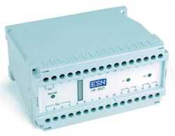
Product Name: ESN Type 8521 Potential Monitoring Device
Brand: ESN
Product Code: Type 8521
Tags: ESN
ESN Type 8521 Potential Monitoring
ESN 8521 Potential
ESN Type Potential Monitoring Device
Type 8521
ESN Type Potential Device
ESN Type Monitoring Device
ESN Type Potential Monitoring Device
8521 Monitoring Device
Type Monitoring
ESN Monitoring Device
ESN 8521 Potential Monitoring Device
Type Potential
Type Potential Device
Type Monitoring Device
ESN Type Monitoring
ESN 8521 Potential Monitoring Device
ESN Type Potential Device
Potential Monitoring Device
8521 Potential
Artikel: 210100
Potential Monitoring Device
您对制造商ESN的产品ESN Type 8521 Potential Monitoring Device,代码为Type 8521感兴趣吗?立即联系我们获取报价。Imtek Engineering,世界上最快最可靠的工业设备供应商,将为您提供最佳报价!
Get Offer With E-Mail: info@im-tek.com
Get a offer for ESN Type 8521 Potential Monitoring Device from our live support team now!
Potential monitoring device as per DIN EN 50122 part 1 / VDE 0115 part 3As protection from dangerous body currents generated from contact voltages/tapping voltages,maximum voltages have been stipulated depending on the effect time. Technical Data Dimensions W / H / D 150 / 73 / 113 mm Housing material Terminal board: polycarbonate lower section: ABS Fastening 2 drilled holes as per drilling tem- plate Standard support rails as per DIN EN 50022 Protection Housing: IP 40; terminals: IP 10 Connections 2 x 2.5 mm2 solid to DIN 46288 or 2 x 1.5 mm2 Ambient temp. - 20°C to + 60°C Power supply AC 19.2 ... 253 V, 50 – 60 Hz, ? 5.5 VA DC 19.2 ... 253 V, ? 2.5 W Measuring input ? 1500 V, continuous; resistance: approx. 2 M? Relay outputs 2 change-over contacts (u), poten- tial-free voltage current cos ? AC 250 V4.0 A > 0.7 DC 120 V 1.0 A ohmic load Displays Network LED green K1: LED yellow K2: LED yellow voltage level: bar graph array Test voltage Supply voltage - measuring voltage outputs: 6 kVe? Input voltage DC 50 V < UM < DC 90 V K1 switches after 295 ... 299 s (workshop) DC 100 V < UM < DC 140 V K1 and K2 switch after 295 ... 299 s UM > DC 140 V K1 and K2 switch jointly as per diagram UM > DC 660 V K1 and K2 switch after max. 30 ms AC 25 V < UM < AC 40 V K1 switches after 295 ... 299 s (workshop) AC 50 V < UM < AC 70 V K1 and K2 switch after 295 ... 299 s UM > AC 70 V K1 and K2 switch jointly as per diagram UM > AC 842 V K1 and K2 switch after max. 30 ms Diagram see overleaf Ordering Information Type 8521 Order No. 210100