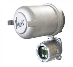
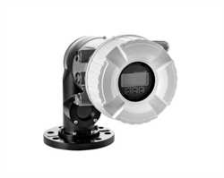
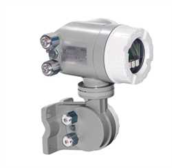
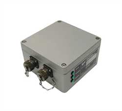
The 2920 Float & Tape Transmitter (FTT) provides data from the tank side to the control room for use in inventory management applications. It accurately converts mechanical level measurement from the connected tank gauge, integrates temperature and HART devices, and provides digital inputs and digital outputs for the indication of alarms or drive relays.Specifications
Accuracy & Repeatability
± 1/16? (1.58 mm)
Range
0 to 120 ft; Meters: 0 to 36 m
Limit switch range is 100 ft (30 M) maximum
Communications
Mark/Space
EIA?485/GSI Type MODBUS®
Biphase Mark
L&J Tankway
Power
Standard: 20 to 65 VDC 0.05A
Optional: 40 to 65 / 110 / 220 – 240 VAC
750 mW nominal, 50/60 Hz
Built-in galvanic isolation for both AC and DC models
Temperature Input
High?accuracy 20?bit analog?to?digital converter. 3?wire RTD Copper (CU90, CU100) or Platinum (PT100).
Discrete Inputs
Enables connection to ancillary devices, such as switches, pumps or valves
Standard: (DC Unit) Option: Two (2) discrete inputs.
Optional: (AC Unit): 4 discrete inputs
Host signal: Open/Closed
Contact Outputs
Triggers temperature or level alarm lights, horns, etc.
Optional (AC Unit): Four (4) software?driven contact outputs
Host signal: Open/Closed
Ratings:
0.6 A @ 125 Vac
1 A @ 30 Vdc
0.6 A @ 110 Vdc
I/O
Analog Input (x1) 4 to 20 mA
Analog Output (x2) 3.5 to 22 mA
HART
HART master for ancillary devices
Typically 4 max, depending on current consumption
Limit Switches
11 amp ? 125, 250, 277 VAC
4 amp ? 125 VAC Tungsten filament Lamp
Load: 1/3 HP ? 125 VAC, 250 VDC
Load: 1/2 amp ? 125 VDC, 1/4 amp ? 250 VDC
Approvals
cFMus (USA & Canada) ? Explosion proof: Class I, Division 1, Groups C&D T5 ?25 °C ? Ta ? +85 °C
Flameproof, Class I, Zone 1, AEx/Ex d IIB T5 ?20 °C ? Ta ? +85 °C
ATEX/IECEx (International) – Flameproof, Class I, Zone 1, Ex II 2G, Ex d IIB T5 Gb ?20 °C ? Ta ? +85 °COptions
01 Approvals
cFMus
ATEX/IECEx
02 Power Input
DC
AC
03 Communications
EIA-485 MODBUS/GSI Type MODBUS®
Biphase Mark
Mark/Space
Tankway (L&J)
04 Limit Switches
None
Two (2) SPDT Limit Switches (180° adjustable dwell, positive activation)
Four (4) SPDT Limit Switches (180° adjustable dwell, positive activation)
05 Limit Switch Range
Not Applicable
0-25 ft
0-50 ft
0-100 ft
0-7.5 m
0-15 m
0-30 m
06 Digital I/O
None
2 Digital Inputs
4 Digital Inputs + 4 Dry Contact Outputs
07 Analog I/O
None
Analog Input (4-20 mA)
Analog Output (4-20 mA)
Analog Input & Outputs (4-20mA)
08 HART
None
HART Master
09 Display Orientation
Forward Facing
Backward Facing
Side Facing