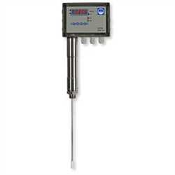
Description
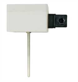
The conductivity switch LRGS 15-1 is a compact system
consisting of a conductivity monitoring electrode and a conductivity switch integrated in the terminal box.
The LRGS 15-1 is used as limit switch and continuous blowdown controller in steam boilers.Technical Data
Service pressure
PN25: 25 barg at 224 °C
Mechanical connection
Screwed ¾", ISO 228-1
Screwed ¾" NPT (optional)
Materials
Screw-in electrode body:
1.4571, X6CrNiMoTi17-12-2 or
1.4404, A 479 316 L (for NPT thread)
Measuring electrode: 1.4571, X6CrNiMoTi17-12-2
Electrode rod insulation: PTFE
Terminal box: Polycarbonate
Measuring length & length of installation
200, 300, 400, 500, 600, 800, 1000 mm
Input
1 Input for resistance thermometer, e. g. TRG 5-53,
measuring insert Pt 100
Measuring range
100 to 10000 µS/cm at 25 °C or 50 to 5000 ppm
at 25 °C
Setpoint
Adjustable between 100 and 10000 µS/cm or
50 to 5000 ppm
MAX limit
Adjustable between 100 and 10000 µS/cm or
50 to 5000 ppm
Switching hysteresis
Controller output: –10 % of the adjusted setpoint
MAX limit: –3 % of the adjusted MAX limitTemperature coefficient Tk
(if a resistance thermometer Pt 100 is connected)
1.6 – 3.0 % per °C, adjustable in steps of 0.1
Supply voltages
230 V, +10 / –15 %, 50-60 Hz
115 V, +10 / –15 %, 50-60 Hz (optional)
Power consumption
5 VA
Fuse
External slow-blow fuse 63 mA at 230 V
External slow-blow fuse 125 mA at 115 V
Output
3 Volt-free relay contacts
5 A 230 V AC / 30 V DC cos ? = 1 (IEC 61810)
Provide contactor with inference suppressor
(RC combination).
Contact material: AgNi 0.15
Indicators and adjustors
1 Four-digit, seven-segment indicator, red, for showing the
actual value (X) / setpoint (W) and status & malfunction
messages
2 Amber LEDs for indicating the actual value (X) /
setpoint (W)
1 Red LED for indicating the MAX limit
2 Green LEDs for indicating “Valve OPEN / CLOSED”
4 Pushbuttons for parameter settings
Cable entry / Electrical connection
Cable glands with integrated cable clamp,
3 x M 16 x 1.5
1 Four-pole screw-type terminal strip for mains connection
1 Three-pole screw-type terminal strip for connecting the
continuous blowdown valve
1 Three-pole screw-type terminal strip for MAX limit
The terminal strips can be detached;
conductor size 1.5 mm2
4 Terminal lugs for connecting the resistance thermometer
Protection
IP 65 to DIN EN 60529
Protection class
2 (protective insulation)
Weight
Approx. 1.5 kg
Ambient temperature
when system is switched on: 0 ° ... 70 °C,
during operation: -10 ... 70 °C
Transport temperature
–20 ... +80 °C (< 100 hours), defrosting time of the de-energized equipment before it can be put into operation: 24 hours.
Storage temperature
–20 ... +70 °C, defrosting time of the de-energized equipment
before it can be put into operation: 24 hours.
Relative humidity
max. 95%, no moisture condensation
Site altitude
max. 2000 m