| Code | Output system |
|---|---|
| Blank | Sink type |
| Item | Specification |
|---|---|
| Power supply voltage | 24VDC |
| Permissible power voltage range | 21.6 ? 30VDC |
| Power consumption | 10W or less |
| Insulation resistance | 20M? or more between external AC power terminals and ground (by 500 VDC insulation resistance tester) |
| Withstand voltage | 500 VAC, 60Hz for 1 minute between external DC power terminals and ground |
| Vibration resistance | 20m/s2 10 ? 500Hz, 10cycles of 5 minutes in 3 directions, conforms to JIS C 0040 standard |
| Ambient operating temperature | 0 ? +55? (No freezing) (Surrounding air temperature rating of 55? maximum) |
| Ambient operating humidity | 20 ? 90 %RH (No condensation) |
| Ambient operating environment | Free from corrosive gases and excessive dust |
| Ambient storage temperature | -10 ? +70? |
| Grounding | Must be securely grounded (ground resistance of 100 ohm or less) |
| Construction | Inside control panel |
| Mounting | Select from two-screw mounting/DIN rail installation/ on-panel mounting using panel mounting fixture VS-K-F. |
| Outside dimension (mm) | 130(W)×81(H)×99(D) |
| Mass | Approx. 0.7kg |
| Item | Specification | |
|---|---|---|
| Converter model | VS-5FXG-1 | |
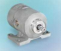
| Applicable sensor | VRE-P028, VRE-P062 | |
| Min. setting units | 0.5° | |
| Number of programs (Panel display) | 16 | |
| Number of switch outputs | 40 | |
| Number of multi-dogs | 10 times for each switch output | |
| Position data sampling time (Permissible speed) | None | 0.176ms(900 r/min when ON/OFF range is 1 degree) |
| Effective number of switches: 5 points SW Nos. 1 ? 5 | 0.176ms(900 r/min when ON/OFF range is 1 degree) | |
| Effective number of switches: 10 points SW Nos. 1 ? 10 | 0.352ms(450 r/min when ON/OFF range is 1 degree) | |
| Effective number of switches: 5 points (ON/OFF independent) SW Nos. 1 ? 5 | 0.352ms(450 r/min when ON/OFF range is 1 degree) | |
| Switch output setting method | Settings are specified by numeric inputs or by teaching. | |
| Setting value memory | Non-volatile memories | |
| Error detection | Memory error, Sensor error, No setting, Setting impossible | |
| Advanced angle function | Pattern | Settings by points |
| No. of points polygonal line | 20 points per switch (switch No.1 ? 10) | |
| Effective speed range | 0 ? 6000r/min | |
| Resolution | 0.5° | |
| Speed setting unit | 1 r/min | |
| Max. advanced angle | ±180° | |
| Top dead center stop angle function | Pattern | Settings by points |
| No. of points polygonal line | 30 points per program | |
| Effective speed range | 0 ? 6000 r/min | |
| Number of programs (Panel display) | 16 | |
| Speed setting unit | 1 r/min | |
| Max. slippage correction range | 7200° | |
| Angle setting unit | 0.5° | |
| Communication function | Serial (RS-232C) communication (setting value saving or loading, monitoring, operation commands)Connection by Mitsubishi-only protocol/MELSEC-A protocolConnection with angle display unit (NDP) is also possibleConnection by OMRON-only protocolConnection with touch panel is possible (VARIMONI) | |
| Auxiliary functions | External origin set function Timing pulse functionMotion detection switch output functionHysteresis functionProtected switch functionSwitch output enabling functionExternal error cancel inputArbitrary pulse output functionCurrent position value output (BCD, gray code (720-division)) / Speed output (binary code)Advanced angle functionTop dead center stop functionPassword functionEnhanced password function | |
| Max. sensor cable length | Standard | 100m |
| Robotic(RBT) | 100m | |
| Item | VS-5FXG-1 | Description | |
|---|---|---|---|
| Input signals | Program No. | 4points | Inputs the exteral program No. |
| Hold or external origin set | 1point | Input to prevent current position from changing or for origin setting. | |
| Error cancel | 1point | Input to cancel an error display. | |
| Switch output enable | 1point | Switch signal will be output only upon the input of this signal. | |
| Slippage correction disabled | 1point | Release the clutch for "Slippage correction" when using the top dead center stop function. | |
| Clutch ONN | 1point | ON/OFF signal outputs occur in accordance with setting values. | |
| Output signals | Switch outputs / Arbitrary pulse output | 40points | ON/OFF signal will be output based on the switch setting value, or pulse signal will be output based on equally dividing a single rotation (division selectable from 1 ? 360). |
| Timing pulse / Motion detection switch | 1point | 60, 180 or 360 pulse signals will be output per rotation, or ON/OFF signal will be output based on the speed setting value. | |
| System ready | 1point | Outputs when controller and sensor are functioning normally. | |
| Program No. | 4points | The currently selected Program No. is output. | |
| Current position value (BCD, gray code (720-division)) Speed Binary output | 11points | Current position (3-digit BCD + 0.5-deg display) signal will be output, or rotational speed will be output in binary code. | |
| Latch pulse | 1point | Outputs a timing signal which ensures that the current position is read in a stable condition. | |
| Slippage correction | 1point | During top dead center control, the brake timing signal output is triggered by the clutch ON signal input. | |
| Item | Input specifications | Item | Output Specifications | ||
|---|---|---|---|---|---|
| Input signals | Program No. External origin set Current position HOLD Error cancel Switch output enable Slippage correction disable Clutch ON | Output signals | Switch output or arbitrary pulse Program No. Sysytem ready Slippage correction | Motion detection switch or timing pulse | Current position value (BCD, gray code (720-division)) or speed (binary) latch pulse |
| Input circuit | DC input, photo-coupler isolation | Output circuit | Transistor (open-collector), photo-coupler isolation | ||
| Input logic | Negative logic | Output logic | Negative logic | Negative logic | Positive logic*1 |
| Rated input voltage | 24VDC | Rated load voltage | 24VDC(30VDC max.) | ||
| Rated input current | 10mA | Max. load current | 100mA | 100mA | 10mA |
| ON voltage | 10VDC or more | Max. voltage drop when ON | 2.0V | 1.5V | 0.7V |
| OFF voltage | 4 VDC or less | ||||
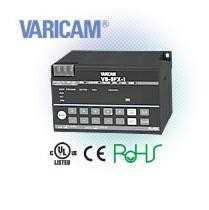
Cam Switch Output Controller
Get the best price and fastest delivery for NSD VS-5FXG-1 VARICAM Cam Switch Output Controller from NSD. Imtek Engineering offers worldwide industrial equipment supply with expert support.